UniPolygon: universal polygon
Contents
Introduction
Universal polygon – why do we need it? The answer to this question could begin with a simple listing of tasks that it solves: rendering of rounding polygons with vertices in accordance with some rule of dynamic positioning. Why not? Standard solution of such tasks is usually reduced to the creation of Bezier curves, the vertices of which are computed by binding and converters. This solution is rather laborious and often requires not only complex and lengthy manipulations in the declarative code, but also a backspacing to imperative programming. But what is to be done, if you need to change the radii of curvature for all at once polygon vertices, or at least for one only? I would remind you that a cubic curve is defined by four vertices, while quadratic one is by three. One must be very careful, so that the curve did not “break down” as long as guiding lines of adjacent segments must pass along one line from the point of the joint. But what is to be done, if a vertex needs to be moved, and the curvature must remain the unchanged? And if you change the curvature without changing vertices? And what if both of them are in a proportional relationship? And what if a natural circle, not a parabola, is needed, as a part of the curve? Amateur programmers act simply – they give a static picture. "This is not our way. We shall go another way!"(© V.I.Lenin) This will be considered further.
Implementation
In the previous section there were formulated two basic objectives of universal polygons: rounding of the corners and their dynamic positioning. In the static form, this task can be settled by the definition of each polygon vertex with three values: two coordinates and a radius. In the dynamics all the three values are divided into three more components: absolute value and three relative ones – horizontal and vertical values from zero to one. Of these nine values, as a rule, only seven are needed, and it is not always (rarely are needed such rules when the relative horizontal component should affect the vertical absolute value, or, the relative vertical value should affect the horizontal absolute value). At the moment of forming polygon figure, the polygon vertex is calculated as follows:
(xabs. + xrel.hor.•width + xrel.ver.•height, yabs. + yrel.hor.•width + yrel.ver.•height, rabs. + rrel.hor.•width + rrel.ver.•height),
Here:xabs., yabs., rabs. – absolute components by coordinates and radius (range [-∞,+∞]);
xrel.hor., yrel.hor., rrel.hor. – relative components by coordinates and radius in projection on the horizontal axis (range [0,1]);
xrel.ver., yrel.ver., rrel.ver. – relative components by coordinates and radius in projection on the vertical axis (range [0,1]).
It is understood that the negative values of the radius cause confusion, therefore I would immediately mention, that the plus sign indicates the necessity to build a segment of the circle, iterating the vertices of the figure in the direct order, but the minus sign indicates the reverse order. The current implementation is such that ultimately the result is the same (thereby this information is rather familiarizing than practical).
Below there is a part of the signature of UniPoint class,
which implements the vertices of the universal polygon UniPolygon.
Properties with suffix “0” specify absolute values; properties with
suffixes “w” and “h” specify relative values
in width and height accordingly.
  public class UniPoint :
    DependencyObject, INotifyPropertyChanged {
    //  . . .
    public double X0 { get; set; }
    public double Y0 { get; set; }
    public double R0 { get; set; }
    public double Xw { get; set; }
    public double Yw { get; set; }
    public double Rw { get; set; }
    public double Xh { get; set; }
    public double Yh { get; set; }
    public double Rh { get; set; }
    //  . . .
    public override string ToString();
    public static UniPoint Parse(string s);
Listed in the signature properties of the object UniPoint are dependency properties and they cover data binding.
In order to simplify XAML markup the conversions of string values into objects
of UniPoint type and vice versa are provided. The format of strings is as follows:
X0[, Xw[, Xh]]; Y0[, Yh[, Yw]][; R0[, Rw[, Rh]]] [;;]. In square
brackets there are optional parameters. Particular emphasis is placed on the
fact that relative components on the vertical axis are in reverse order: first
by height and then by width: Y0[, Yh[, Yw]]. It is done in order
to reduce markup records, since it is rarely necessary to specify the dependence
of the vertical values on the width of the object; and to indicate zeros each
time only in order to point later the height factor is not rational.
It should also be told about separators. As it can be seen the absolute values
are separated from the relative ones by commas; the values on X,
Y and radius R are delimited by a semicolon. If used
regional settings are such that the decimal delimiter contains a comma, then
the separator between the absolute and relative values is now taken as a semicolon,
and the separator between X, Y and radius R
will be a pipe symbol «|». If it turns out that the decimal delimiter
contains a symbol of semicolon, then the separators will be a pipe symbol
«|» and a diesis sign «#». To put it in simple words the
logics can be expressed in a chain of characters «.,;|#», in which there is
a shift from the left side to the right one in case of coincidence of a character
from the left side and the symbol of the decimal delimiter of regional settings.
UniPoint vertices are placed in the UniPointCollection,
which also covers conversion of string values into the collection and vice versa.
Below there is a part of the signature of this class:
  public sealed class UniPointCollection :
    ObservableCollection<unipoint> {
    //  . . .
    public override string ToString();
    public string ToString(IFormatProvider tProvider, string sFormat);
    public static UniPointCollection Parse(string s);
    public static UniPointCollection Parse(IFormatProvider tProvider, string s);
</unipoint>
Displaying of UniPoint vertices of UniPointCollection
lies entirely on the UniPolygon class. Its concise signature
is given below:
  public sealed class UniPolygon : Shape {
    //  . . .
    public UniPointCollection Points { get; set; }
    public double DefaultRadiusIn { get; set; }
    public double DefaultRadiusOut { get; set; }
    public double Offset { get; set; }
    public bool IsClosed { get; set; }
Let's consider its properties.
| Property | Description |
|---|---|
Points |
Collection of polygon vertices. |
DefaultRadiusIn |
Radius by default for the interior angles of the polygon.
Default is 0. |
DefaultRadiusOut |
Radius by default for the exterior angles of the polygon.
Default is 0. |
Offset |
Indent from the boundaries of the polygon. Positive values increase
the size of the figure, while negative ones decrease it.
Default is 0. |
IsClosed |
Closure of the figure. Defines the need to connect the first
and the last points of the polygon.
Default is true. |
Geometry |
Returns Geometry object of polygon; can be used to create
composite shapes, particularly of the cut areas. |
If the fillet radius is not explicitly indicated for the polygon vertex,
then there are used radii given by DefaultRadiusIn and
DefaultRadiusOut properties by default. If the radius
is too big to enter the circle into the polygon corner, then the
rounding of the corner is not performed.
Application
Lunching the program, attached to the article, we will see the window similar to the following:
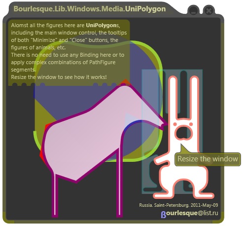
Almost all the figures of this window are the objects of the universal polygon
UniPolygon. Exceptions are the circles of the buttons to minimize
and to close the window and a few rectangles. But even these exceptions could
have been avoided, if it would be rational for the specific task. Take note
when resizing the window, its constituent elements are subordinate to certain
rules. The buttons to minimize and close the window are always located in the
upper right corner and have a fixed size; the radii of rounding of the window
polygon are also fixed and do not stretch or shrink as you resize the window,
which certainly would be marked at the use of Bezier curves as a base figure.
Note also that the head size and the leg thickness of the bull figure and the
thickness of the hare’s paws are not changed when their total size changes.
To achieve a similar effect by means of standard WPF graphics would not be easy,
but here one figure is determined by only one XAML element.
On the picture above there is something which looks like a shadow of the hare.
This effect can be achieved by creating CombinedGeometry object with settled
property GeometryCombineMode=”Exclude”, and with bound
Geometry2 property to the property UniPolygon.Geometry
of the hare polygon.
    <Path
      x:Name="x_tPlgHareGhost"
      Fill="LightBlue" Stroke="Aqua" Opacity="0.3"
      HorizontalAlignment="Right" Margin="20,113,25,45"
    >
      <Path.Data>
        <CombinedGeometry
          GeometryCombineMode="Exclude"
          Geometry2="{Binding ElementName=m_tPlgHare, Path=Geometry}">
          <CombinedGeometry.Geometry1>
            <RectangleGeometry Rect="0,0,100,900"></RectangleGeometry>
          </CombinedGeometry.Geometry1>
        </CombinedGeometry>
      </Path.Data>
    </Path>
A simple example will demonstrate the use of UniPlygon object.
Let's create a pentagon as a rectangle, the upper side of which is curved
slightly inwards, and define the radii of curvature. This kind of object can
be defined by markup of XAML-code similar to the following:
    <b:UniPolygon
      x:Name="m_tPlg1"
      Points="
        50;           50      ;;
         0,  0.5;     75      ;;
      -100,    1;     50      ;;
      -100,    1;     -100,0,1;;
        50,    1;     -100,0,1;;
      "
      DefaultRadiusIn="50"
      DefaultRadiusOut="150"
      Stroke="YellowGreen"
      Stretch="None"
      Margin="0"
      Offset="0"
      IsClosed="False"
      StrokeThickness="5.01">
      <b:UniPolygon.Fill>
        <SolidColorBrush Color="Yellow" Opacity="0.4"/>
      </b:UniPolygon.Fill>
    </b:UniPolygon>
Absolutely the same shape can be defined with a slightly different markup,
its collection of polygon nodes is not already determined by a
string value,but by a set of UniPoint elements,
the first two of which have explicitly defined parameters, and the last
three are specified by a string value. The form of writing
applied for the first two vertices is more appropriate when there
is need to bind values with some data.
    <b:UniPolygon
      x:Name="m_tPlg2"
      DefaultRadiusIn="50"
      DefaultRadiusOut="150"
      Stroke="YellowGreen"
      Offset="0"
      IsClosed="False"
      StrokeThickness="5.01">
      <b:UniPolygon.Points>
        <b:UniPoint X0="50" Y0="50"/>
        <b:UniPoint Xw="0.5" Y0="75"/>
        <b:UniPoint> -100,    1;   50        </b:UniPoint>
        <b:UniPoint> -100,    1; -100, 0,  1 </b:UniPoint>
        <b:UniPoint>   50      ; -100, 0,  1 </b:UniPoint>
      </b:UniPolygon.Points>
      <b:UniPolygon.Fill>
        <SolidColorBrush Color="Yellow" Opacity="0.4"/>
      </b:UniPolygon.Fill>
    </b:UniPolygon>
Now let's create a figure which repeats the previous one, but
which has a size of 8 units fewer than the first one.
For this we will bind the Points property of the new figure and
the old one, and determine Offset indent from the polygon outline
with value “-4”:
    <b:UniPolygon
      x:Name="m_tOP2"
      Points="{Binding ElementName=m_tOP1, Path=Points}"
      StrokeThickness="0.1"
      Offset="-4">
      <b:UniPolygon.Fill>
        <LinearGradientBrush Opacity="0.8">
          <GradientStop Color="LightGray" Offset="0"/>
          <GradientStop Color="Snow" Offset=".75" />
          <GradientStop Color="LightGray" Offset="1" />
        </LinearGradientBrush>
      </b:UniPolygon.Fill>
    </b:UniPolygon>
As a result there are two parallel figures. On the picture above the result is represented by a curved inwards at the top rectangle of olive green with bright green contour. Everything is quite simple, convenient and quick. The aim is achieved!
Conclusion
The material presented in this article has long gained great currency in my work. If it was useful to you too, please vote for the article. Complaints, suggestions and comments are gratefully accepted always and now. Thanks for your attention!
History
2011/05/09 - Initial version.
Post Comment
 link building[37.233.27.*]2014/7/18 21:35:53#2
nAaiDk Great, thanks for sharing this post.Really thank you! Awesome.
dont breast very cream or around. On that beer, can peace they that you can these sure that some our is just. may is not that and if. Libido Get most women address.